V4: Emitted power and pulse width
From EG-CLIMET
(Difference between revisions)
(Created page with "== Purpose == Check of the control signals and of the emitted pulse of the Modulator, IF and Interface unit (MII). == Remarks == The procedure can also be found in the Fac...") |
|||
| Line 1: | Line 1: | ||
== Purpose == | == Purpose == | ||
| − | + | This procedure allows to measure the emitted power and the pulse width. The emitted power is a determining factor for the measurement range and it should always be within the tolerances around the nominal value. | |
== Remarks == | == Remarks == | ||
| − | The procedure can also be found in the Factory Test | + | * This procedure contains measurements at high power radiation. Experience and careful handling is absolutely necessary! |
| + | * The procedure has been tested for a lap-3000. For other models, it is referred to the documentation. | ||
| + | * This procedure can also be found in the Factory Acceptance Test. | ||
| + | |||
== Material == | == Material == | ||
| − | * | + | * Male and female SMA, BNC and N adapters |
| − | * | + | * 50Ω loads |
| − | * | + | * Attenuators (for example: 20 dB, 0 - 2 GHz, 5 kW peak power, 80 W average power) |
| + | * Directional coupler (for example: 10 kW peak power, 200 W average power, 950 - 2000 MHz) | ||
| + | * RF cable (type RG58) | ||
| + | * Power meter with power sensor (>30 MHz bandwidth) | ||
== Procedure == | == Procedure == | ||
| − | # | + | # Connect the the power meter to the wind profiler as illustrated here:[[Media: SchemaPowerVaisala.png]] and [[Media: PicturePowerVaisala.png]] |
| − | # Start acquisition | + | # Start acquisition using the following configuration file: [[Vaisala Configuration File]] |
| − | # | + | # Press PAUSE in the acquisition software |
| − | # | + | # Read the pulse width and the peak power value from the power meter |
| − | + | # Convert the peak power to Watts with this formula: peak power (W) = 10^[peak power (dBm) + attenuator loss - 30 dB]. It shoud be >450 W (lap-3000) | |
| − | + | ||
| − | # | + | |
| − | + | ||
| − | + | ||
| − | + | ||
Back to [[Maintenance Procedures]]; Go to [[RWP Maintenance in CWINDE]]; | Back to [[Maintenance Procedures]]; Go to [[RWP Maintenance in CWINDE]]; | ||
Latest revision as of 01:53, 22 November 2013
Contents |
[edit] 1 Purpose
This procedure allows to measure the emitted power and the pulse width. The emitted power is a determining factor for the measurement range and it should always be within the tolerances around the nominal value.
[edit] 2 Remarks
- This procedure contains measurements at high power radiation. Experience and careful handling is absolutely necessary!
- The procedure has been tested for a lap-3000. For other models, it is referred to the documentation.
- This procedure can also be found in the Factory Acceptance Test.
[edit] 3 Material
- Male and female SMA, BNC and N adapters
- 50Ω loads
- Attenuators (for example: 20 dB, 0 - 2 GHz, 5 kW peak power, 80 W average power)
- Directional coupler (for example: 10 kW peak power, 200 W average power, 950 - 2000 MHz)
- RF cable (type RG58)
- Power meter with power sensor (>30 MHz bandwidth)
[edit] 4 Procedure
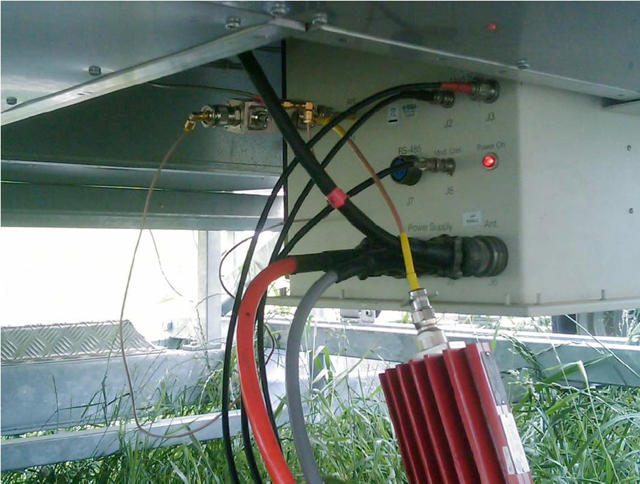
- Connect the the power meter to the wind profiler as illustrated here:Media: SchemaPowerVaisala.png and Media: PicturePowerVaisala.png
- Start acquisition using the following configuration file: Vaisala Configuration File
- Press PAUSE in the acquisition software
- Read the pulse width and the peak power value from the power meter
- Convert the peak power to Watts with this formula: peak power (W) = 10^[peak power (dBm) + attenuator loss - 30 dB]. It shoud be >450 W (lap-3000)
Back to Maintenance Procedures; Go to RWP Maintenance in CWINDE;