V3: Radar signals
From EG-CLIMET
Contents |
1 Purpose
Check of the control signals and of the emitted pulse of the Modulator, IF and Interface unit (MII).
2 Remarks
The procedure can also be found in the Factory Test Procedure.
3 Material
- RF cables (RG58 type) with BNC and N connectors
- Oscilloscope (2 channels, bandwidth > 100 MHz)
- Logic timing diagram of your wind profiler (for lap-3000 Media:SchemaLogicTimingVaisala.png)
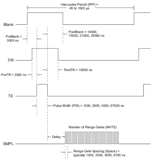
4 Procedure
- Terminate the TRANSMIT OUTPUT port with a 50Ω load
- Start acquisition and press PAUSE
- Connect channel 1 of the oscilloscope to TX
- Measure pulse width and inter pulse period (IPP)
- Connect channel 2 of the oscilloscope to SMPL
- Measure the delay
- Measure the time (spacing) between two sample pulses (ch2)
- Measure the total time of the sample pulses (sample period) and the number of sample pulses
- Connect channel 2 of the oscilloscope to BLANK
- Measure the period of blanking before and after the TX pulse
Back to Maintenance Procedures; Go to RWP Maintenance in CWINDE;