Cloud radar fundamentals
Contents |
1 Fundamentals
Basics of radar principles and their application in meteorology are described in e.g. Battan (1973), Sauvageot (1992), Bringi & Chandrasekar (2001), Lhermitte (2002), Rinehart (2005), and Doviak and Zrnic (2006). For a general overview about cloud radars the reader is referred to Kropfli and Kelly (1996), Kollias et al (2007), and Görsdorf (2007).
Meteorological radars transmit electromagnetic radiation. A part of this transmitted radiation is scattered back to the radar by atmospheric particles. The intensity and phase of the backscatter waves depends on the number, size and properties of the particles and the radar characteristics as for example wavelength and transmit power. The frequency for cloud radar operation is restricted to atmospheric windows where absorption of radar signals by atmospheric gases is minimal. Atmospheric windows relevant for milimeter cloud radars exist at 35, 90 and 135 GHz (Figure 1) (Ulaby et al. 1981), whereas the 35 GHz and 94 GHz band are preferred for cloud radar operation.

2 Radar Equation
The radar equation for for a beam-filling meteorological target is
 (1)
(1)
with
 : transmitted power,
  : received power, g: gain,
  : wavelength,
  : horizontal and vertical beamwidth of the antenna (measured in radians), r: distance to the sample volume from the radar, h: pulse length corresponding to the duration t of the transmitted pulse (h=c·t, with c the speed of light), D: droplet diameter
K is a parameter related to the complex index of refraction of the material. It is given by
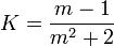 (2)
(2)
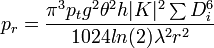
If the diameter of all the cloud droplets in a unit volume is known equation (1) can be used to calculate the power received from a sample of cloud droplets. However, in reality the diameter of all the cloud droplets in a unit volume is not known. To solve this problem, the radar reflectivity factor Z is defined as
 (3)
(3)
The radar reflectivity factor Z is independent of the radar and only depends upon the number and sizes of the cloud droplets.
Substituting equation (3) into equation (1) yields
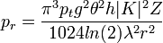 (4)
(4)
This equation can be applied to any radar, provided the particles meet the Rayleigh assumption. Instead of using the pulse length h, the pulse duration t is often used.
To compress the very large value range of Z logarithmic values are used instead of linear values.
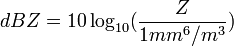 (5)
(5)
3 Doppler effect
New radars provide direct measurements of the speed of movement of targets by using the Doppler effect. The Doppler velocity is the power-weighted mean of the radial velocities  and is related to the Doppler frequency
  by
by
 (6)
(6)
where f is the frequency of the radar and c the speed of light. The range r between the radar and the target is determined by the time T the signal needs to travel to and back from the target:
 (7)
(7)
4 Polarization
Modern cloud radars can also transmit and receive radiation in selected polarization states. This allows to determine the depolarization ratio which may give information on the shape, the fall orientation, the size, the refractive index and the bulk density of the scatterers. For linear polarization measurements the differential reflectivity
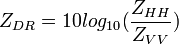 (8)
(8)
is a measure for the anisotropy of the scatterers and their orientation. The linear depolarization ratio provides additional information on particle shape, orientation and the dielectric constant
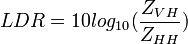 (9)
(9)
with  : cross-polar return at vertical polarization for horizontally polarized transmission,
  : co-polar return at horizontal polarization for horizontally polarized transmission,
  : co-polar return for vertical polarisation.
5 Pulse radar and FMCW radar
The electromagnetic radiation can be transmitted as single pulses (pulse radar) or continuously with a time dependent modulation of the frequency (FMCW, Frequency Modulated Continuous Wave) radar. Pulse radars take advantage of the time between two transmit pulses to receive the reflected signal and use the same antenna for transmitting and receiving. FMCW radars require two antennas, because they transmit and receive a continuous signal. The pulse repetition time and the sweep time for frequency modulation are usually of the same order of magnitude, and thus the signal-to-noise ratio is comparable for both radar types. The advantage of FMCW radar is, that only a low transmit power needs to be generated to obtain the same sensitivity as a pulse radar. A comparison between pulse and FMCW radars can be found in Russchenberg (1992).
Back to Cloud radar