D1: Losses in Tx chain
From EG-CLIMET
(Difference between revisions)
(Created page with "== Purpose == This procedure allows to determine losses in the transmit chain at low power. It helps to identify eventually broken components in the transmit chain (e.g. circ...") |
Latest revision as of 01:59, 22 November 2013
Contents |
[edit] 1 Purpose
This procedure allows to determine losses in the transmit chain at low power. It helps to identify eventually broken components in the transmit chain (e.g. circulator, antenna switch, cables).
[edit] 2 Remarks
This procedure tests all the elements along the signal path: cables inside the outdoor cabinet, circulator, VSWR coupler, antenna switch and finally the antenna cable. An alternative to this method would be to measure the S21 parameter using an S-parameter analyzer set at the radar frequency.
[edit] 3 Material
- Spectrum analyser
[edit] 4 Procedure
- Stop acquisition
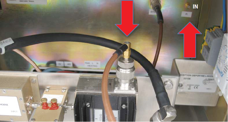
- Disconnect the RF signal cable from the input of the amplifier (Media:PictureAmpInputDegreane.png) and connect it to the input of the spectrum analyser
- Configure a one-measurement (vertical beam) wind cycle on PCA (pulse width = 2500 ns)
- Start acquisition
- Measure the peak power with the spectrum analyser (settings: center frequency = 1290 MHz, video bandwidth = 2 MHz)
- Connect the RF signal cable to the circulator input (Media:PictureAmpInputDegreane.png)
- Disconnect the cable from the divider of the vertical antenna and connect it to the spectrum analyser
- Measure the peak power
- Repeat step 3 and 8 for each antenna
Go to Maintenance Procedures; Go to RWP Maintenance in CWINDE;